 Metal Spinning
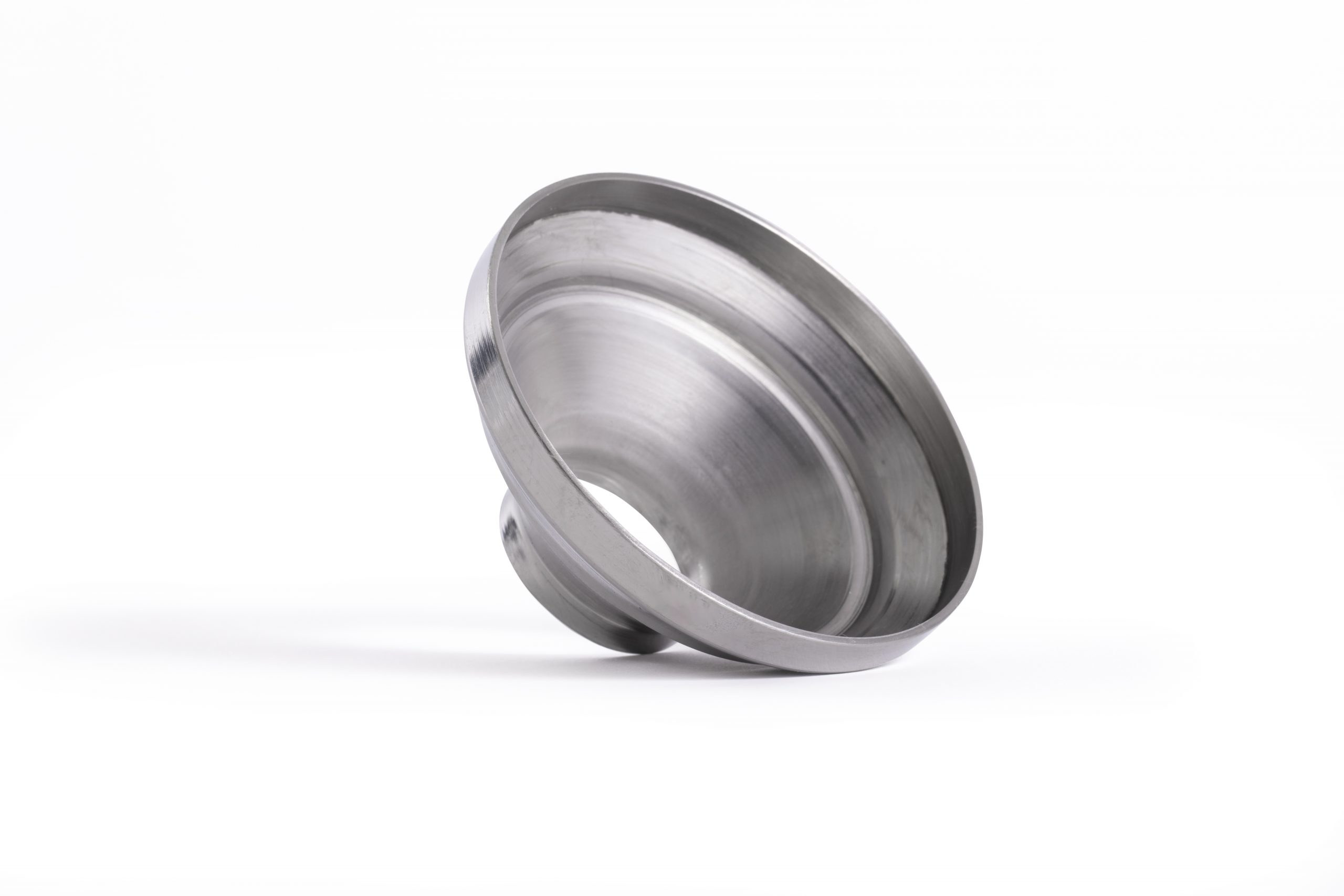 Bespoke Metal Spinning
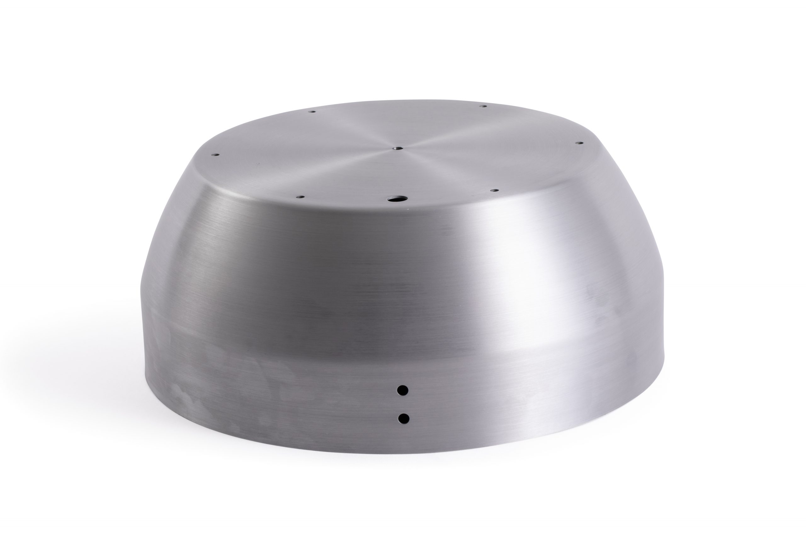 Metal Polishing
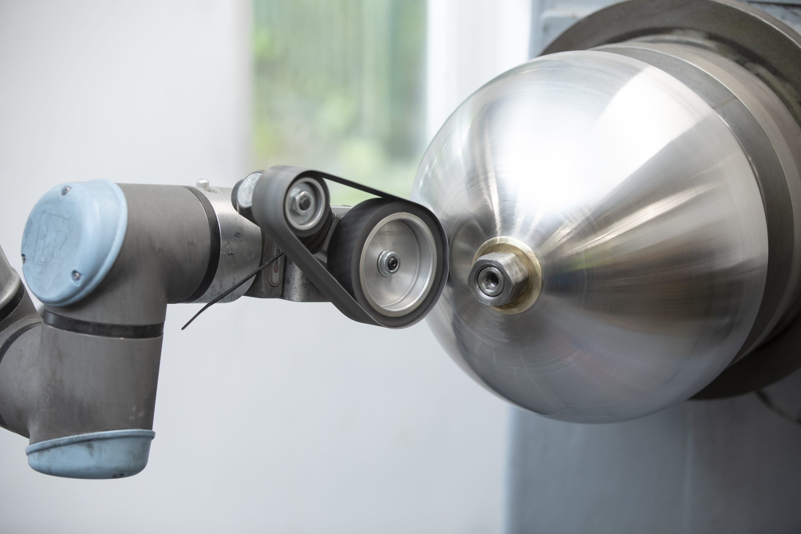
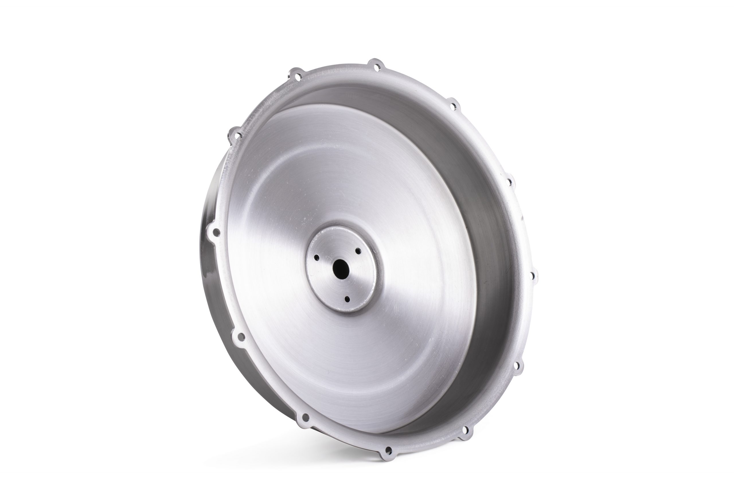 Machining
 Metal Pressing
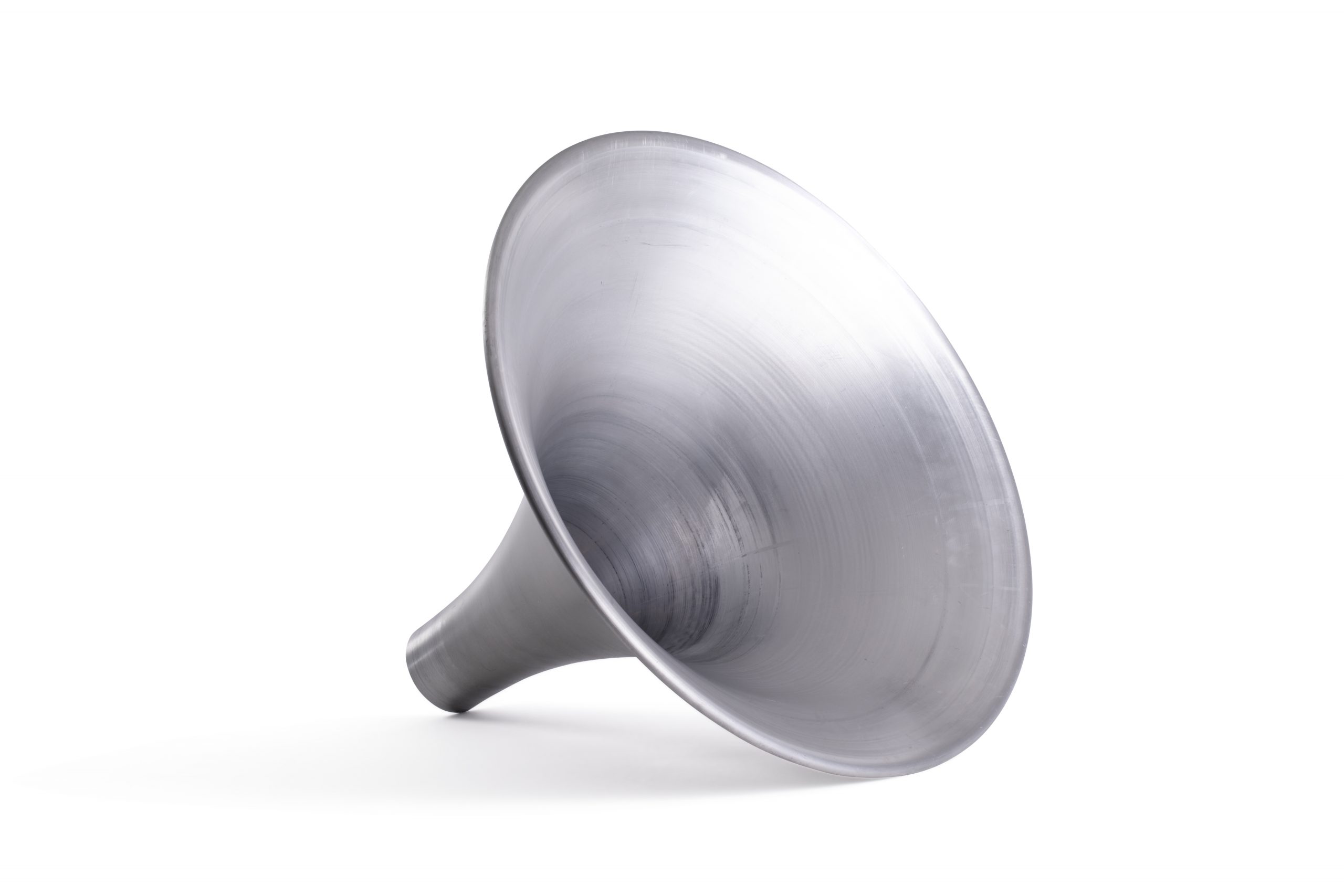 Metal Swaging
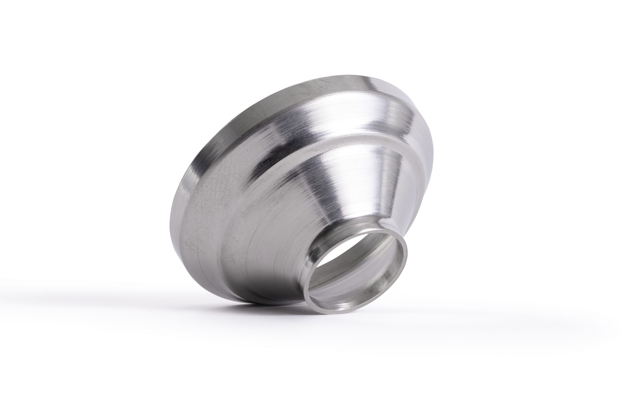 Metal Fabrication & Welding
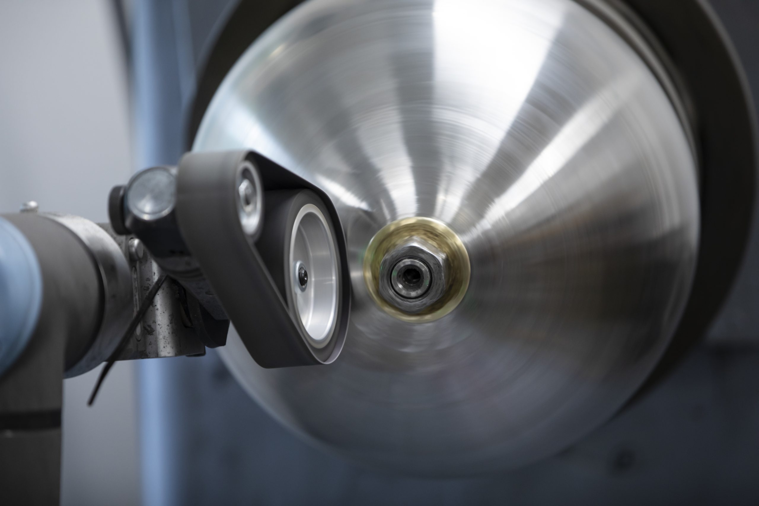 Precision Engineering
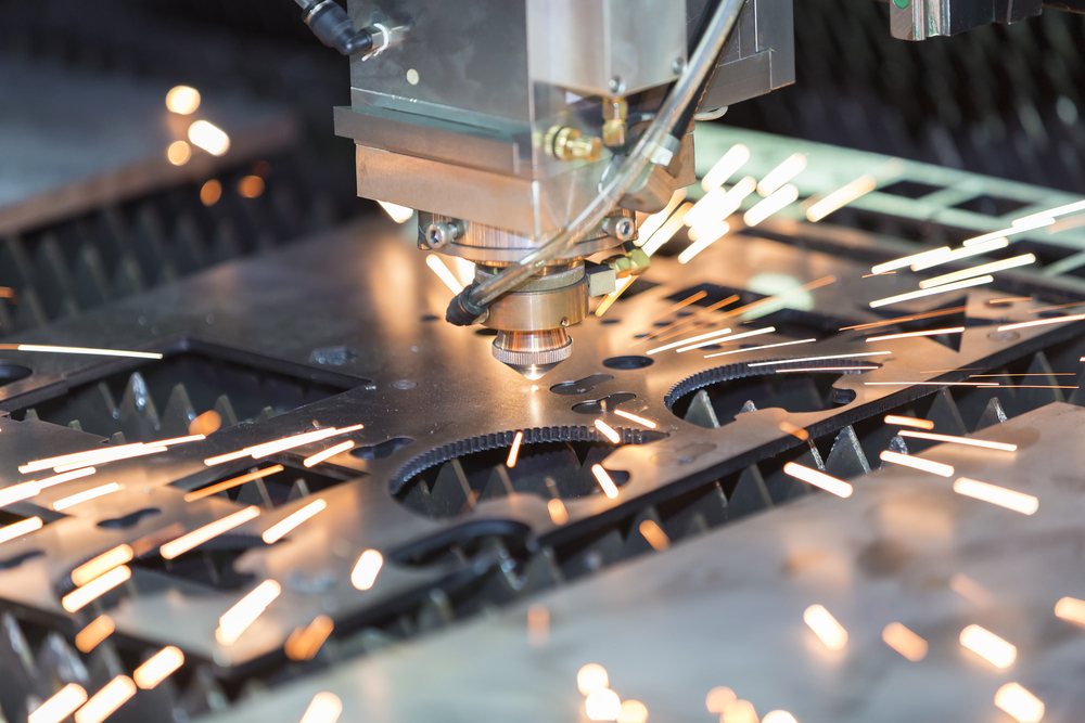 Laser Cutting
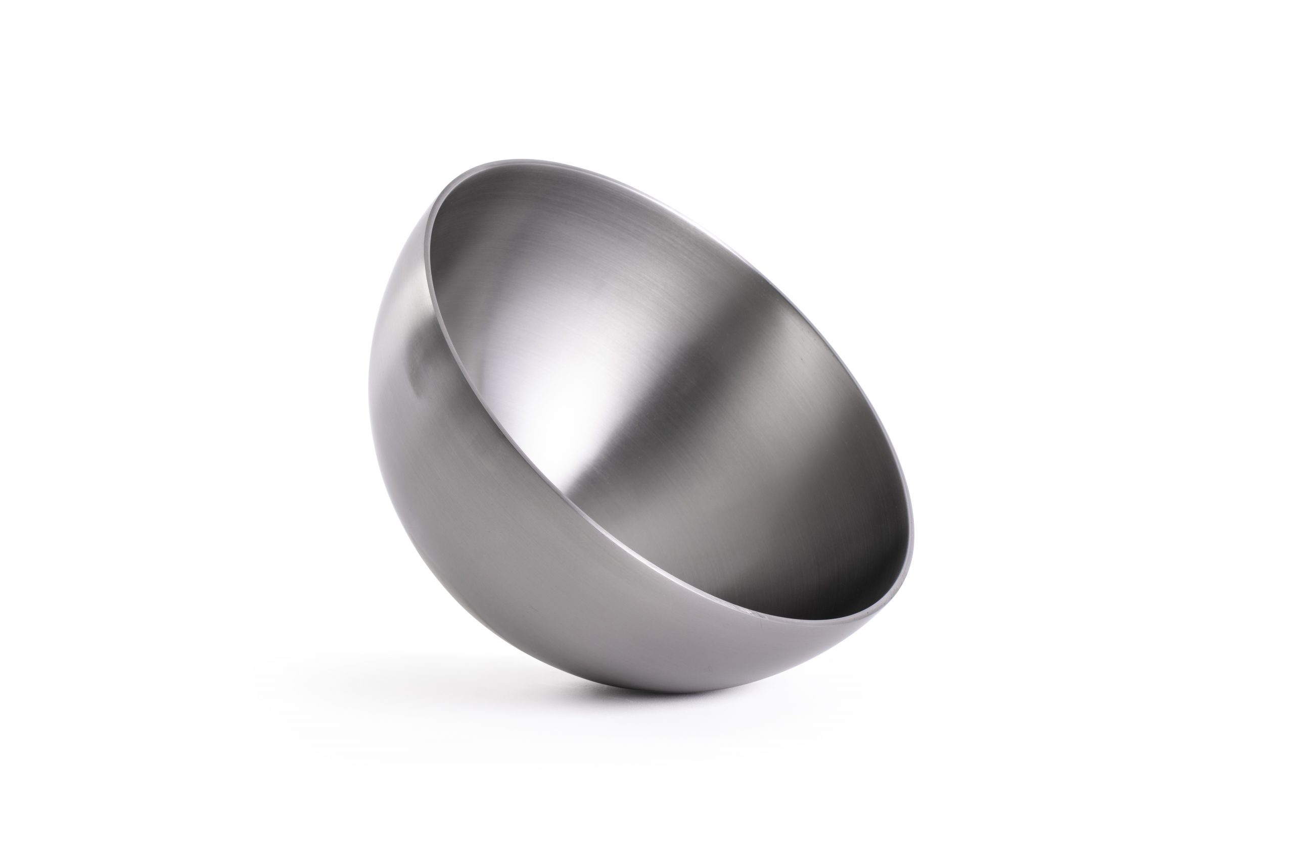 Inspection and Quality
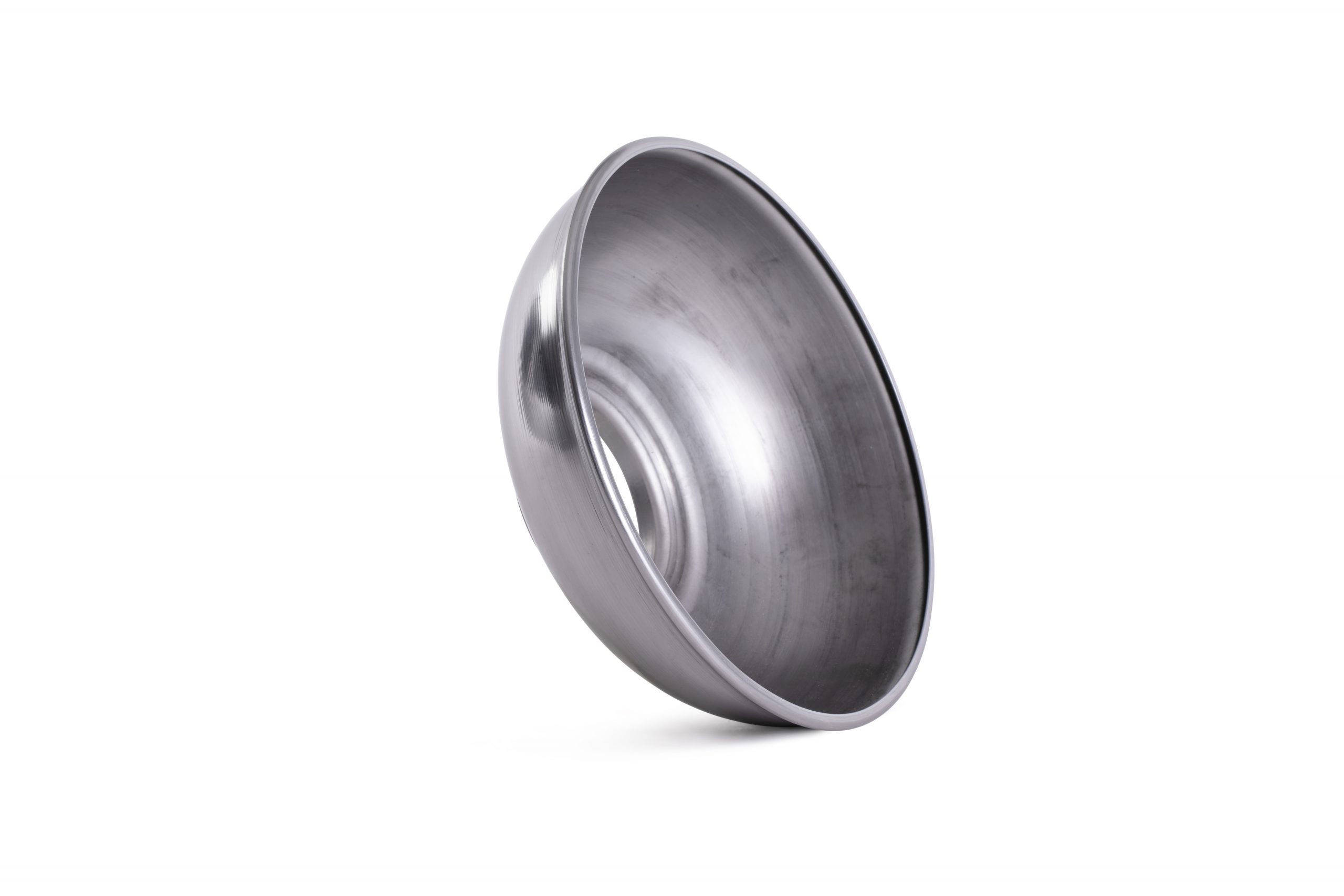 Anodising, Electropolishing and Pickling & Passivating
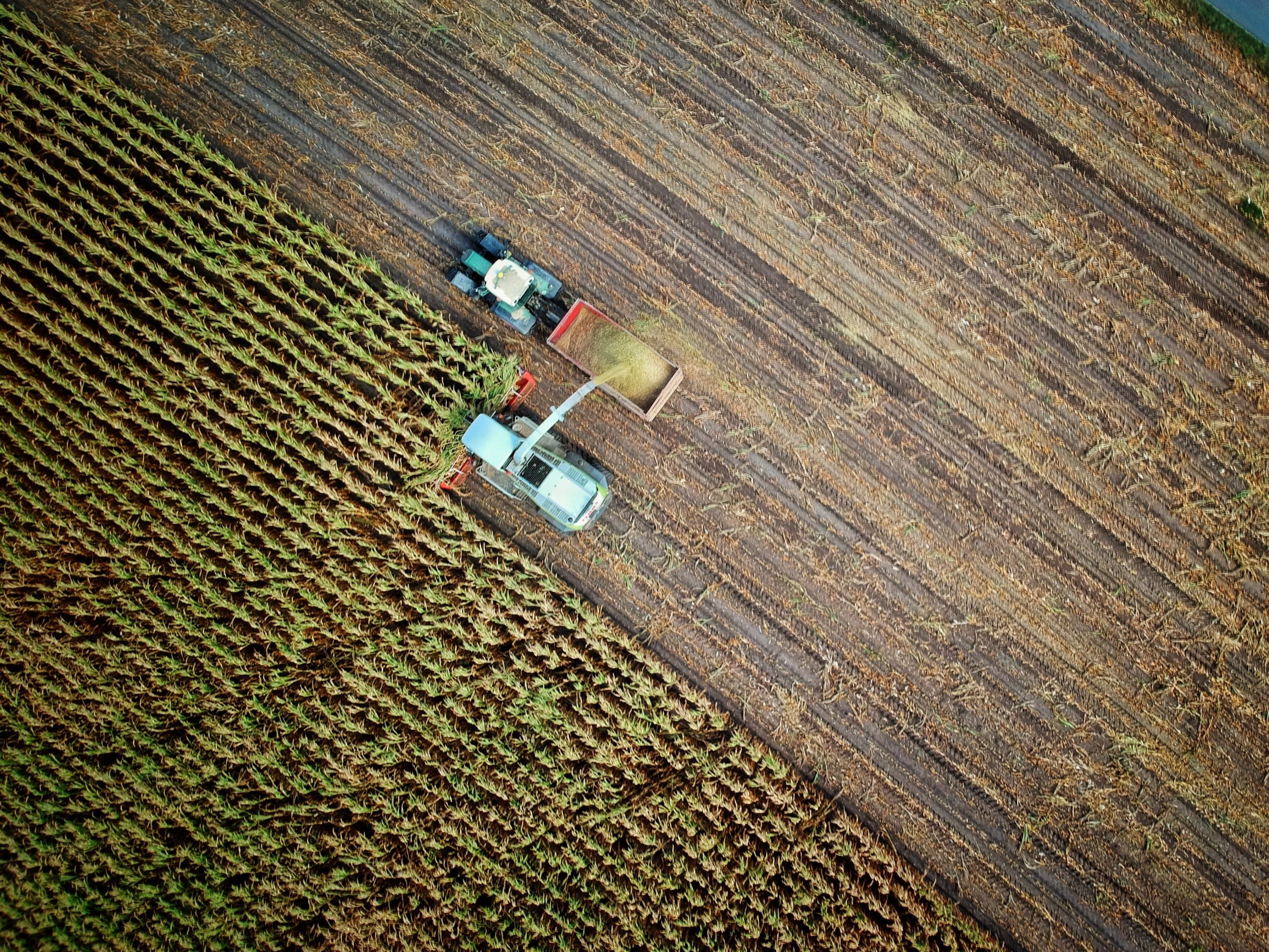 Agriculture
 Automotive
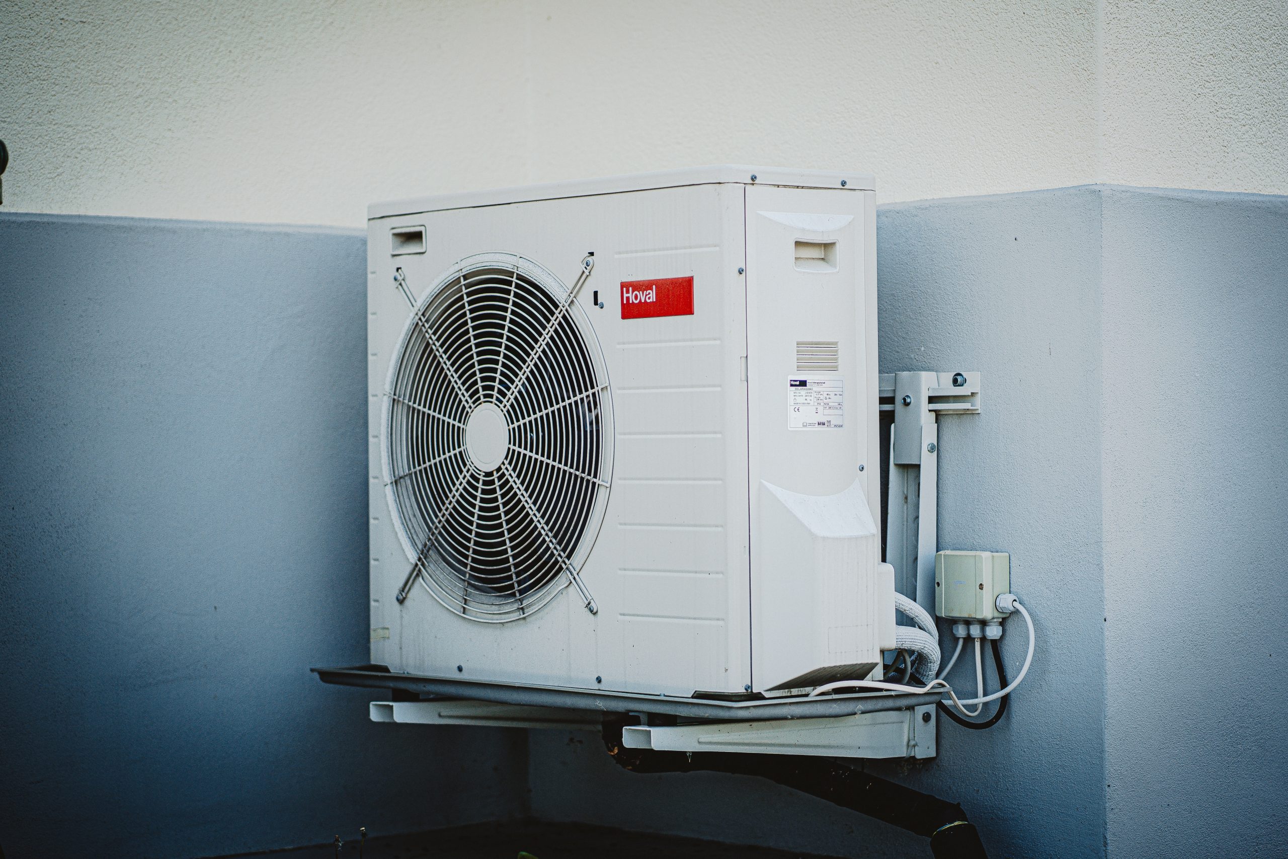 Air Movement
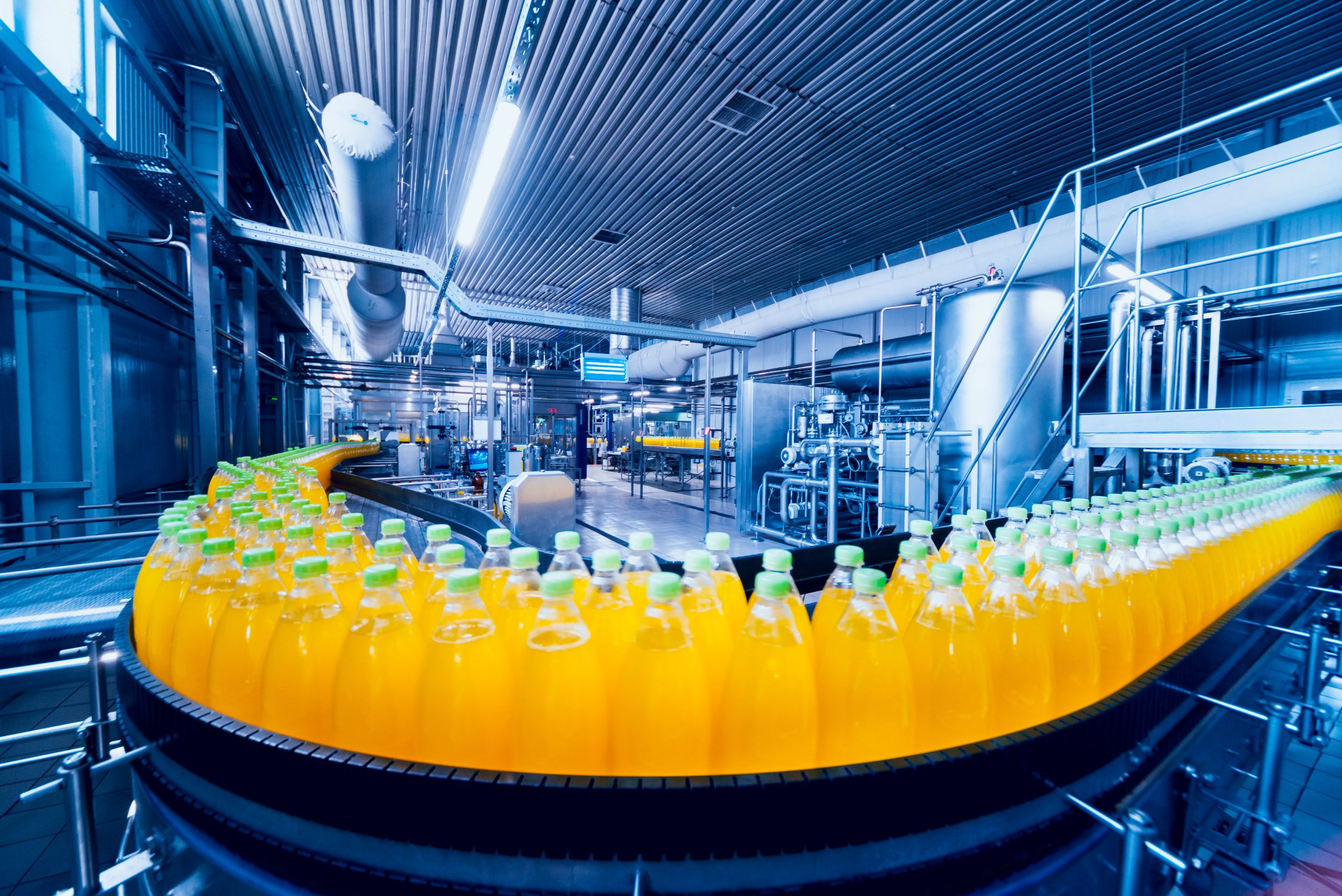 Food Industry
 Marine
 Medical and Cryogenic
 Playground
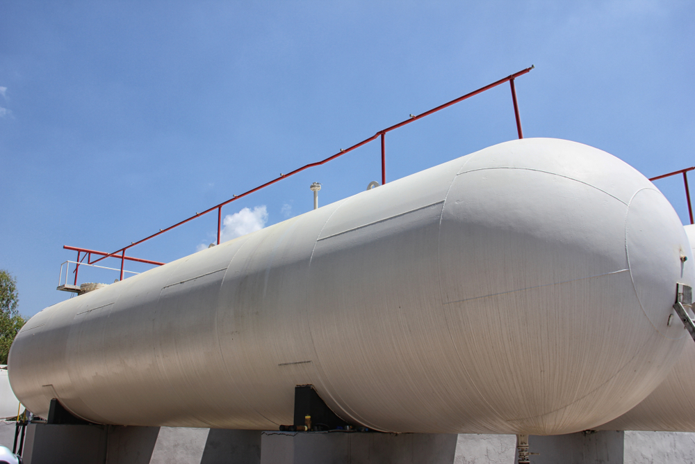 Pressure Vessels
 Renewable Energy
 Safety
Using Spun Components in Food and Beverage Equipment: Hygiene, Weld Reduction, and Cleanability
23/03/26
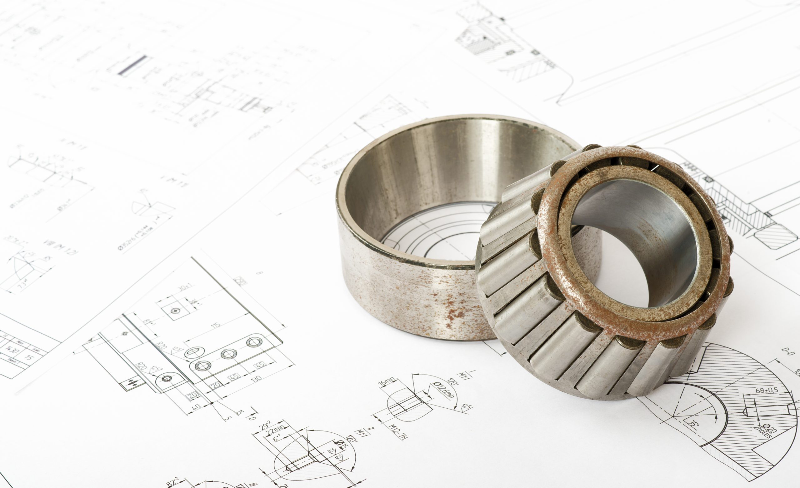
In the world of metal spinning, getting accurate, timely quotes can significantly accelerate your project timeline, from concept to production. At Tanfield Metal Spinners, a leading UK-based specialist since 1984, we pride ourselves on delivering 90% of quotes within 24 hours. This speed is possible thanks to clear, comprehensive information from our clients. While we don’t strictly require customer-provided drawings, our technical engineering department can create free drawings based on your specifications for approval, submitting well-prepared CAD files or technical drawings often streamlines the process even further.
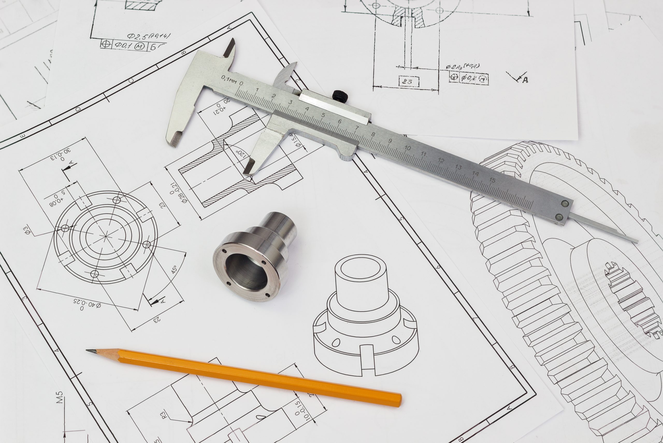
Poorly defined designs lead to back-and-forth questions, clarifications, and delays. Conversely, a properly prepared submission allows our experts to assess feasibility, material needs, tooling requirements, and costs quickly and accurately. This blog post provides practical guidance on preparing CAD models and technical drawings specifically for spun components. By following these best practices, you’ll help ensure faster, more precise quotes and smoother collaboration with manufacturers like Tanfield Metal Spinners.
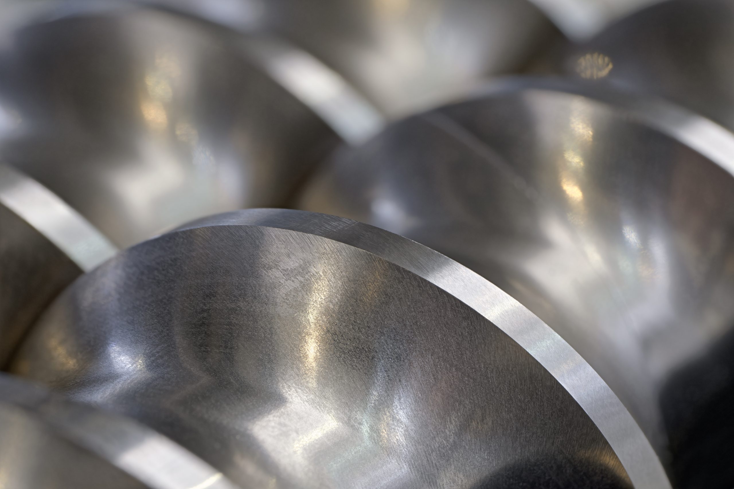
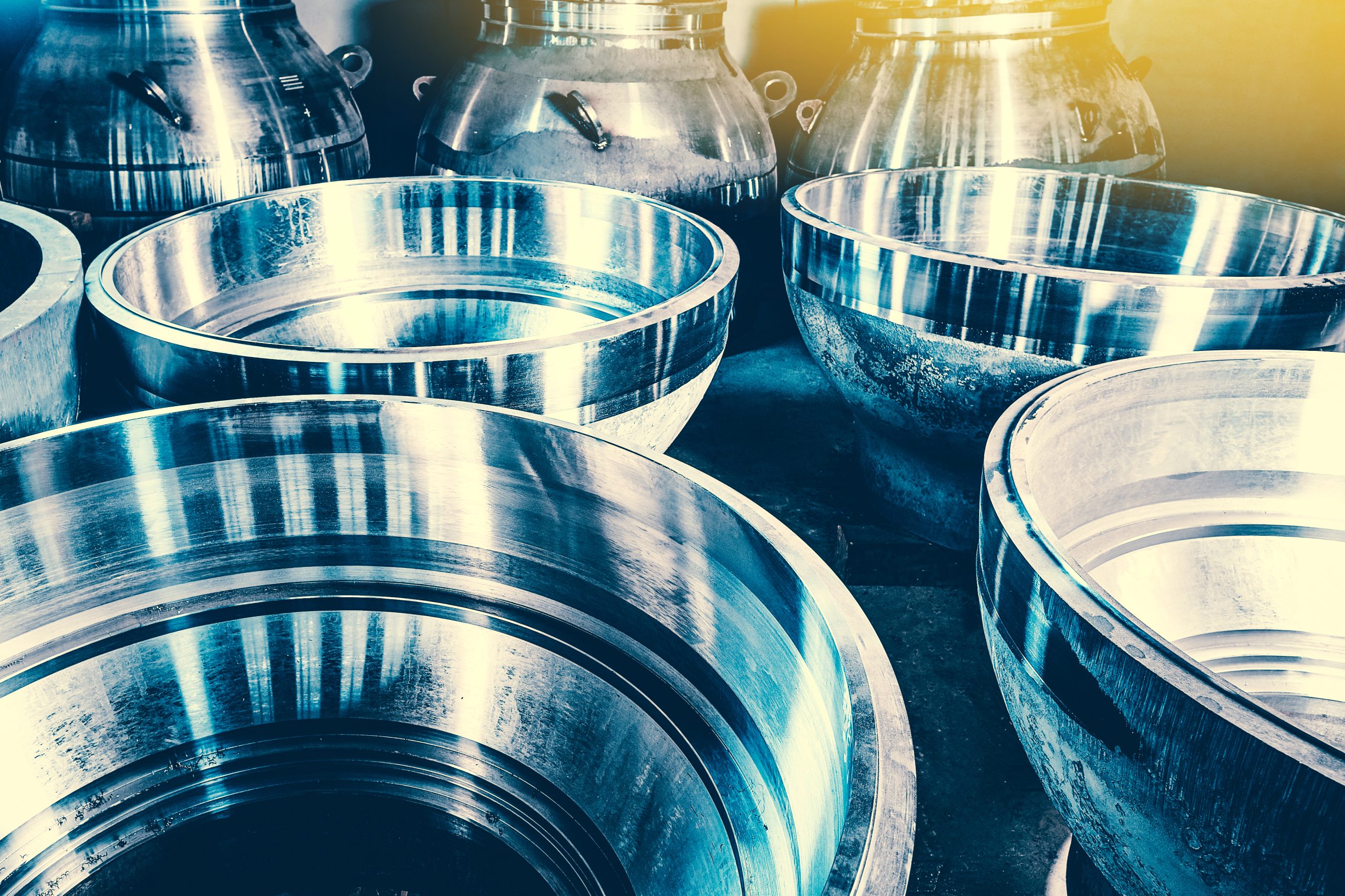
Before diving into file preparation, it’s essential to grasp what makes a component suitable for metal spinning. The process excels at producing axially symmetrical, round, hollow shapes from flat metal blanks. Common components include dished ends (ellipsoidal, hemispherical, torispherical), pressure vessel hemispheres, metal cones (typically 60–150° angles), tank heads, funnels, and cylindrical sections.
Key design considerations:
Designs that ignore these fundamentals often require revisions, slowing quotes. Start by confirming your part aligns with spinning’s strengths; seamless, lightweight, high-strength parts with excellent surface finish.
Tanfield accepts a variety of formats, but compatibility speeds things up. Recommended options include:
Avoid sending only sketches, images, or low-resolution PDFs without dimensions—these trigger requests for more detail. If you’re unsure about formats, provide what you have; our engineers can often work from basic specs and produce a drawing for your sign-off.
A clear technical drawing acts as the blueprint for quoting. Include these essentials:
Use standard drawing conventions: title block with part name, drawing number, revision, date, scale, and your company details. Avoid overloading with unnecessary construction lines—focus on manufacturable features.
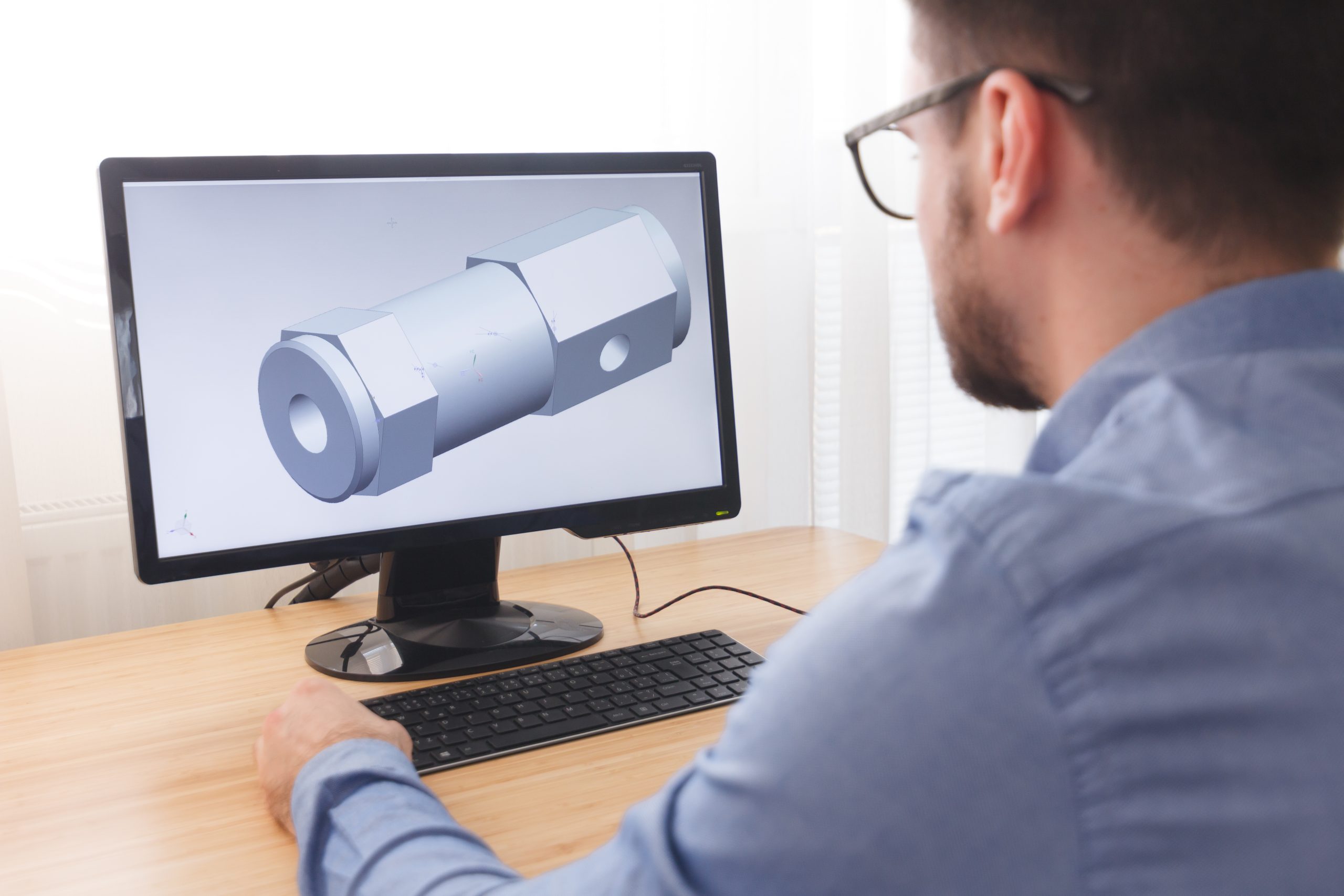
For 3D CAD files, follow these tips to make them quote-ready:
If your CAD software supports it, export with PMI (Product Manufacturing Information) embedded for tolerances and notes.
Many delays stem from these pitfalls:
By addressing these upfront, you reduce clarification rounds.
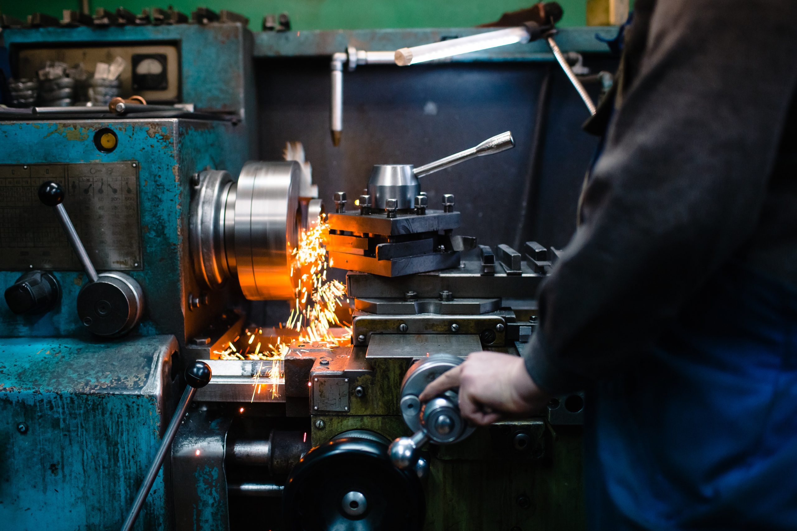
When you contact us, via our website form, email (talktoanexpert@metal-spinners.com), or phone (0191 419 3377), provide your files and specs. Our team reviews them promptly. If no drawing exists, we can generate one free for approval. We assess tooling (often none needed for standards), material availability, and production method (automated spinning for consistency).
Quotes include methodology, pricing, and lead times (typically 3-4 weeks standard). Full traceability, ISO 9001 accreditation, and material certification come standard.
Preparing CAD and technical drawings thoughtfully for spun components isn’t just about compliance—it’s about efficiency. Clear submissions enable manufacturers like Tanfield Metal Spinners to quote faster, recommend optimisations, and deliver high-quality, seamless parts with minimal revisions.
Whether you’re designing dished ends for pressure vessels, cones for material handling, or custom hemispheres, starting with precise documentation pays dividends. Our 35,000 sq-ft facility and automated capabilities are ready to bring your designs to life.
Ready to get a quote? Visit metal-spinners.com, upload your files, and describe your project. We’ll respond swiftly, often within 24 hours. Let’s turn your ideas into spun reality efficiently.